|
|

|

|
|||
|
|
|
|
This file is used for interfacing with CAD systems other than AutoCAD. It also contains the default values of TaskEdit, default display distances between nested layouts and Auto-Bridge.
A sample .DXF file is required. To create sample.dxf file, open a drawing called SAMPLE in the particular CAD software used and do a “DXF-OUT” equivalent command.
Format for ANEST.SET
#
# AutoNEST V9
# Filename = anest.set
#
# 1. Shape dxf sample filename
# 2. Shape dxf option (1 BLOCK/0 ENTITIES)
# 3. Nested layout dxf sample filename
# 4. Nested layout dxf option (1 BLOCK/0 ENTITIES)
# 5. Insertion point 0: Shape box center; 1:Fix insertion as below; 2:Use DXF “INSBASE” value
# 6. Insertion point x and y
# 7. Layer option (1 to set default layer name)
# 8. Name of default Layer
# 9. Layer name of Enclosing Rectangle of nested layout
# 10. Color of Enclosing Rectangle of nested layout
#
sample
0
sample
0
1
0.00 0.00
1
1
$ENCL_RECT_RESERVED_LAYER$
7
@TASK
$NULL$ # Default Title
$NULL$ # Default Job Ref Name
$NULL$ # Default Project Name
$NULL$ # Default Client
$NULL$ # Default Drawn By
$NULL$ # Default Material Grade
$NULL$ # Default Thickness
$NULL$ # Default Unit Weight
0.00 0.00 # Default Cutting Gap and Shear Blade Limit
0.00 0.00 0.00 0.00 0.00 # Default Edge Allowance (Left, Right, Bottom ,Top) & ir-stock
C R 1 3 0 0 1 0 600.0000 600.0000 0 0.00 # Default Nest Options (format :same as in .JOB)
STOCK = # Default Stock Format : STOCK = Width x Length Qty Priority Cost-per-Stock
IR_STOCK = # Default Ir-Stock Format : IR_STOCK = Name Qty Priority
0 # Default Multi Stock option- 0:Auto; 1: Extended Best Yield; 2: Extended Lowest Cost
1 # Default Part +180 Orientation 1:Support +180; 0:No
5 # Default Nesting Step Angle (Integer, Recommended:5, Range:0 to 360)
ALL # Default Part Orientation (0 90 180 or step 3 0 360 or ALL)
1 # Default Part Pairing: 1: Yes; 0: No
3 1 5 # Default Stock Priority, Ir_stock Priority and Part Priority
WxL # Stock Format for IMPORT STOCKS. Accepted formats: WxL or LxW
0 # Top-up if stocks are insufficient : 1: Yes; 0: No
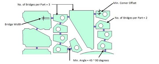
@BRIDGE
0 # View nesting result with bridge
10.0 0.25 # Default bridge width (metric imperial)
20.0 0.5 # Default corner offset (metric imperial)
45.0 45.0 # Default minimum angle betw. bridge and part profile (metric imperial)
5 5 # Default maximum allowable no of bridges per part (metric imperial)
0.0 0.0 # Default maximum bridge length (metric imperial)
@SKELETON_CUT
750 750 20.0 20.0 # Default X-Spacing and Y-Spacing of Skeleton-Cut-Off (metric imperial)
10 0.5 # Default value for Skeleton-bridge or offset from part profile (metric imperial)
300 300 12.0 12.0 # Default min-X and min-Y for Skeleton Cut-Off & Shear Cut (metric imperial)
0.5 # Nearest Cut-Off to edge of stock for clearance(range: 0-1). Factor of Spacing.
20 0.5 # Min length of Cut-Off (metric imperial)
0 # 0: Default; 1: To edge of Encl Rect (if partially packed)
900 2.25 # Default min area of Scrap-pocket (metric imperial)
9500 36.0 # Default max area of Scrap-pocket (metric imperial)
13.0 0.5 # Default Min length of Scrap-pocket (metric imperial)
45.0 # Maximum angle between vectors
@COMMONLINE
TOOL_PATH 3 1 5 # Default Layername, Color of Horz-Toolpath, Color of Vert-Toolpath, Color of Toekick/non-rectangle
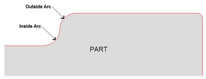
4.0 0.175 # Toekick - min radius for outside arc (metric imperial)
3.0 0.125 # Toekick - min radius for inside arc (metric imperial)
@LAYOUT
1.1 0 # Horz Display Ratio between layouts (0:based on individual stock length; 1:based on longest stock length)
40 # Report length of Layout Summary
1.2 # Vert Display Ratio between rows ( based on the biggest stock width )
0 # Max no. of layouts displayed per row (0: no limit)
1 # Location of Layout Summary ( 1:Right; 2:Top-Left; 3:Top-Right )
0 # 1: Display part's tool profile for common-cut; 0: Do not display
1 # 1: Show Cost in Layout & Task Summary reports; 0: Do not show
1 # 1:Display Auto-numbering of Shear cutting sequence ; 0:Do not display
25.0 1.0 # Min clearance (to nearest Stock)to draw Shear Cut Lines (metric imperial)
0 # 0:Show complete list of Stocks on-screen and in reports; 1:Show Used Stocks only on-screen; 2: Show Used Stocks only on-screen and in reports
@OTHERS
1 # ViewNEST prompt - 1: Auto-Bridge Only; 2: Auto-Bridge/Common-Line
1 0 # ViewNEST Skeleton-Cut-Off prompt - 1:Yes, 0:No; Default answer 0:None, 1:Skel-Cut-Off, 2:Scrap-pkt, 3:Both
Lines starting with # character denote 'Comments'. The 'AutoNEST V9’ must be in one of the comment lines. There is no limit to the number of comment lines.
Line 1 and 3 |
These are template DXF files created by your particular CAD system. DXF support for each CAD system may differ slightly, AutoNEST requires these templates from sample DXF files to generate a fully compatible .DXF file. Such DXF file should be loaded with all the necessary information, e.g. linetypes, layers, etc.
|
Line 2 |
Refers to DXF format for part/shape geometry files. (1:Block / 0: Entities) For BLOCK representation, the part/shapes must be inserted into the drawing as AutoCAD Blocks. ALL Blocks must be inserted in the “ANEST” layer. The part/shape name will be written into the Block section of the DXF file for that particular part/shape. For ENTITIES format, the part /shape must be drawn using “entities” (eg. LINE, ARC, CIRCLE …etc). Each file should contain 1 part /shape.
|
Line 4 |
Refers to the DXF format of the nested output. (1:Block / 0: Entities)
DXF Option in SYSDATA
For BLOCK format, AutoNEST will copy the part /shape block information from the dxf file of the part/shape only once and insert the part/shape name repeatedly as required into the dxf file of the nested layout. This option will produce a smaller dxf file.
For ENTITIES format, AutoNEST will copy part/shape information from the dxf file of the part/shape and write these information into the dxf file of the nested layout repeatedly. ] For reviewing of nested output within Nest Manager environment, the user can only choose either DXF or VEC File Format option in Sysdata.
VEC Option in SYSDATAFor BLOCK format, AutoNEST will read all points from the VEC file of the part/shape and create a part/shape block in the DXF file of the nested layout. This part/shape block will be inserted repeatedly as required.
For ENTITIES format, AutoNEST will read all points from the VEC file of the part/shape, then copy these points into the DXF file of the nested layout repeatedly when as required.
|
Line 5 |
Denotes to the Reference Point whereby the insertion points of the part/ shapes within the nested layout are referred to.
0 - Use the centre of the enclosing rectangle of the part 1 - Use the insertion point as indicated in line 6 2 - Use the INSBASE variable value from part DXF file
|
Line 6 |
Input of x and y coordinates. |
Line 7 |
1 - assume the layer name in Line 8 when converting .VEC or .STK files to DXF format. |
Line 8 |
Default layer name for DXF files if .VEC or .STK files are converted to DXF format. |
Line 9 |
Default Layer name of the enclosing rectangle of the nested results. If the enclosing rectangle is not required, enter an asterisk character “*” (without the quotes).
|
Line 10 |
Default Color of the enclosing rectangle of the nested results. |
Under @TASK are the Default values for TaskEdit.
Line 1 to 8 |
Not applicable for AutoNEST. |
Line 9 |
The 1st value is the default Cutting Gap. The 2nd value is the default Shear Blade limit.
|
Line 10 |
First 4 values - Default edge allowance for regular stock (Left, Right, Bottom and Top). 5th value - Default edge allowance for irregular stock.
|
Line 11 |
Default values for Nest Options. (same format as .JOB) Nesting control parameters. The 1st parameter is for Single Part nesting.
The 1st parameter can be: ‘D’ - means single part nesting with highest Density (in single array) ‘M’ - means single part nesting with Maximum quantity (in single array) ‘C’ - means single part nesting with Combination of density & maximum quantity (in mixed array) ‘E’ - means extension - long nest.
The 2nd parameter is to specify which type of stock to be used first if there are both Regular Stock and Irregular Stock in the same job/ task. ‘R’ - means nest all Regular Stocks first before any Irregular Stocks ‘I’ - means nest all Irregular Stocks first before any Regular Stocks
The 3rd parameter is for Packing Start Point 1 Left Bottom 2 Left Top 3 Right Top 4 Right Bottom
The 4th parameter is for Packing direction control 1 Horizontal Packing 2 Vertical Packing 3 Auto (System Control) 4 Horizontal Packing for All Stocks 5 Vertical Packing for All Stocks The 5th parameter is for Common Line option0 Without Common Line Consideration 1 With common Line Consideration The 6th parameter is for Mirror option (Single part only)0 Do NOT allow Part Mirror 1 Allow Part Mirror 2 Nest Half Quantity with Mirrored Parts The 7th parameter is for Ignore Part Hole option0 Ignore ‘Hole’ of part (will not nest any parts inside part holes) 1 Do NOT ignore ‘hole’ of part (will nest smaller parts inside part holes) The 8th parameter is for Save Remnant option0 Do NOT save remnant stocks 1 Save remnant stocks into .STK files.
The 9th and 10th parameters are for Min. Remnant Size in X and Y. Only remnant stocks that are greater than this Min. Remnant Size will be saved into .stk files onto the default Part/ Ir-Stock directory and provided the “Save Remnant” option (8th parameter) is set to 1. The 11th and 12th parameters are for ‘Parts Priority Control’.11th parameter is for “Max. No. of Priority per Stock” (Integer >=0 ) 12th parameter is for “Min. Nest-able Remaining Space” percentage. (range : 0.00 to 100.00)
|
Line 12 |
Default Stock specifications for each distinct regular Stock - in the following format :-
STOCK = Width x Length Qty Priority Cost-per-Stock
“STOCK” must be in upper case or capital letters. If the Stock is “coil”, append the “>” character to the Length of the stock size. Example : 2000 x 4000>
If the Stock is non-coil, just give the exact dimension of the stock size. Example : 3000 x 6000
Qty refers to the quantity of each distinct stock available for nesting.
Priority of each distinct stock. 1 has the highest priority whereas 99 has the lowest priority. This refers to the priority for regular stocks only.
Cost-per-Stock refers to the cost for each piece of the stock.
|
Line 13 |
Default Irregular Stock specifications of each distinct irregular stock (ir-stock). Each line has the following format:
IR_STOCK = Name Qty Priority
“IR_STOCK” must be in upper case or capital letters.
Name is the .STK (ir-stock) file name. The .STK file stores the ir-stock geometry profile.
Qty refers to the quantity of each distinct ir-stocks available for nesting.
Priority of each distinct ir-stock. 1 has the highest priority whereas 99 has the lowest priority. This refers to the priority for ir-stocks only.
|
Line 14 |
Default Multi Stock Option (Nest Option)0 Auto 1 Extended - Best Yield 2 Extended - Lowest Cost
|
Line 15 |
Default Part Orientation, with or without +180. 0 Do not support +180 1 Support +180 |
Line 16 |
Default Nesting Step Angle (Integer, range: 0 to 360). The larger the number, the longer the nesting time. 5 (Recommended) |
Line 17 |
Default Part Orientation (0 90 180 or step 3 0 360 or ALL) If there is more than 1 default angles, they must be separated by a SPACE. ALL (reserved word) means all orientations are permissible.
|
Line 18 |
Default Part Pairing. 0 No to Pairing 1 Yes to Pairing (default)
|
Line 19 |
3 Default Stock Priority 1 Default Ir_stock Priority 5 Default Part Priority
|
Line 20 |
Stock Format for IMPORT STOCKS. Accepted formats: WxL or LxW
|
Line 21 |
Top-up stocks if the existing stocks are insufficient: 1: Yes; 0: No (currently not in use) |
@BRIDGE - The next 5 lines after @BRIDGE are the default bridge parameters (in Metric & Imperial English units) for Auto-Bridge. See the following illustration for explanation.
Illustration for Bridge parameters
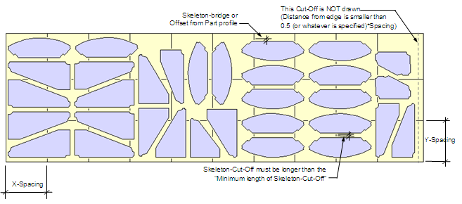
@SKELETON_CUT
750 750 20.0 20.0 # Default X-Spacing and Y-Spacing of Skeleton-Cut-Off (metric imperial)
10 0.5 # Default value for Skeleton-bridge or offset from part profile (metric imperial)
300 300 12.0 12.0 # Default min-X and min-Y (metric imperial)
0.5 # Nearest Cut-Off to edge of stock for clearance(range: 0-1). Factor of Spacing.
20 0.9 # Min length of Cut-Off (metric imperial)
1 # 0: Default; 1: To edge of Encl Rect (if partially packed)
These are the default values for Skeleton-Cut-Off whenever a Task is being created. Each of them are explained below :-
Line 1 |
Default X-Spacing and Y-Spacing.The first 2 values are for Metric units whereas the 3rd and 4th values are for Imperial units. |
Line 2 |
Default Skeleton-bridge or Offset from part profileThe first value is for Metric units whereas the 2nd is for Imperial units. |
Line 3 |
Default minimum X and Y dimension.The first 2 values are for Metric units whereas the 3rd and 4th values are for Imperial units. When there is NO remnant specified, Skeleton-Cut-Off will use these values to ensure that re-useable space (with these X and Y dimensions or more) on the stock will be untouched by Skeleton-Cut-Off. |
Line 4 |
Default Skeleton Cut-Off to the nearest stock edge (range 0 to 1)This value is a factor of the Spacing (eg. 0.5*Spacing). Any skeleton-cut-off that is less than (0.5*Spacing) from the edge of the stock will not be drawn. |
Line 5 |
Default minimum length of Skeleton-Cut-OffThe first value is for Metric units whereas the 2nd is for Imperial units. This is to ensure that any length of Cut-off, smaller than this value will not be drawn. |
Line 6 |
0: Default; 1: To edge of Encl Rect (if partially packed)When the value is set to “0”, skeleton-cut-off will not draw into any re-useable space that is equal or more than the Minimum X and Minimum Y (line 3). When the value is set to “1”, skeleton-cut-off will be drawn – up to the parts’ enclosing rectangle. |
Line 7 |
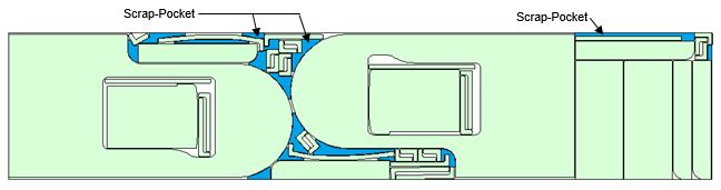
Default minimum area of Scrap-pocket. The first value is for Metric units whereas the 2nd value is for Imperial units.
|
Line 8 |
Default maximum area of Scrap-pocket. The first value is for Metric units whereas the 2nd value is for Imperial units.
|
Line 9 |
Default minimum length of Scrap-pocket. The first value is for Metric units whereas the 2nd value is for Imperial units.
|
Line 10 |
Maximum angle between 2 vectors |
@COMMONLINE
TOOL_PATH 3 1 5 # Default Layername, Color of Horz-Toolpath, Color of Vert-Toolpath, Color of Toekick
/non-rectangle
4.0 0.175 # Toekick - min radius for outside arc (metric imperial)
3.0 0.125 # Toekick - min radius for inside arc (metric imperial)
@LAYOUT - The parameters under @LAYOUT affect how nested results are displayed.
1.1 0 # Horz Display Ratio between layouts (0: based on individual stock length; 1: based on longest stock length)
40 # Report length of Layout Summary
1.2 # Vert Display Ratio between rows ( based on the biggest stock width )
3 # Max no. of layouts displayed per row (0: no limit)
1 # Location of Layout Summary ( 1:Right; 2:Top-Left; 3:Top-Right )
0 # 1:Display part's tool profile for common-cut; 0 :Do not display
1 # 1:Show Cost in Layout & Task Summary reports; 0 :Do not show
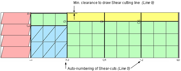
1 # 1:Display Auto-numbering of Shear cutting sequence ; 0:Do not display
13.0 0.5 # Min clearance (to nearest Stock)to draw Shear Cut Lines (metric imperial)
0 # 0:Show complete list of Stocks in Task Report; 1:Show Used Stocks only;
2: Show Used Stocks in Task Report & .sum
Line 1 to 5 |
Parameters that control the display of nested layouts. See the illustrations A, B and C below for an explanation of these parameters. |
Line 6 |
This parameter controls the display of parts (tool-profile) in the nested layout 0 Display Part as per normal 1 Display Part expanded with half cutting gap.
|
Line 7 |
This parameter determines the display of COST of stocks on the nested layout 0 Do NOT show the Cost. 1 Show the COST of stocks.
|
Line 8 |
This parameter controls the display of the Auto-Numbering of Shear cutting sequence on the nested layouts. (see Illustration below) 0 Do NOT display 1 Display auto-numbering
|
Line 9 |
Applicable for Shear Cutting Lines. This is the minimum clearance from the edge of stock to the cutting line in order to draw the cutting line. If the distance is deemed to close to the stock (less than min. clearance), than no cutting line will be drawn.
The first value is for metric units, the second is for imperial units. See Illustration below.
|
Illustration A (based on the above first 5 parameters@LAYOUT)
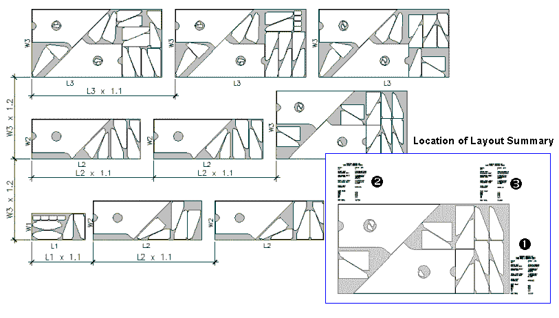
Illustration B - Layout Summary report at “Location 1”
Textsize : Layout Summary textsize as defined in Sysdata. (8th line in ANEST.ARG)
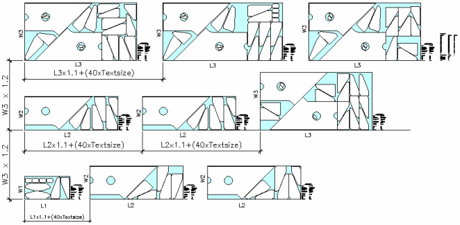
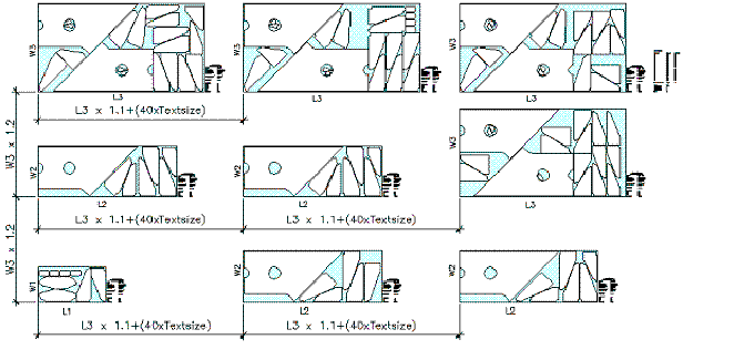
Illustration C - Horz display between layouts based on longest Stock Length
@LAYOUT
1.1 1 # Horz Display Ratio between layouts (0: based on individual stock length; 1: based on longest stock length)
Shear Auto-Numbering & Minimum Clearance (Illustration for Line 8 & 9)
Line 10 |
This is to control the on-screen display of the list of Stocks in the reports. 0 Show complete list of Stocks on-screen and in .SUM report. 1 Show Used Stocks only on-screen. 2 Show Used Stocks only on-screen and in .SUM report. |
@OTHERS - This is the prompt options for the ViewNEST command in the AutoCAD environment.
The 1st line controls the prompt for Auto-bridge and Commonline(Toolpath).
The 2nd line controls the prompt for Skeleton-Cut-off.