|
|

|

|
|||
|
|
|
|
Parts to be cut with a fourth axis may be drawn as you normally would draw a 2-D part unless you are using a standard cut cycle, heli-inside, pocketing, drill motions, etc. In order to use a standard cut cycle, you will need to draw on a surface other than the top by changing the User Coordinate System (UCS) to draw on each face and add thickness to the geometry that is drawn to insure you are on the correct face of the part.
There are 2 main methods when drawing on a horizontal face, Planar (0, 90, 180, 270) and Non-Planar (Any degree).
How to draw on a face/side of a part (Planar):
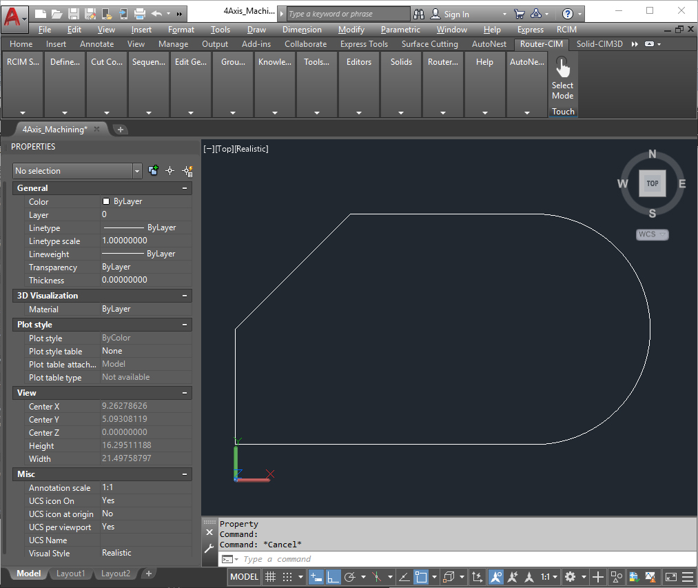
1.Draw the part to be cut as you normally would.
2.Add thickness to the part as described in the process below.
A. Choose the properties manager icon from your "Standard Toolbar" or press Ctrl and 1 at the same time.
1) Move or dock this window to the side of your drawing area so you can see your geometry.
2) Notice that the field at the top of this window says "No Selection"
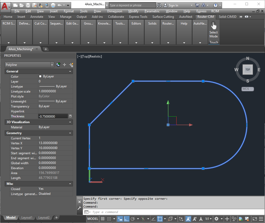
B. Select the whole part by clicking on each segment or making a window around it.
1) Notice that the field at the top of this window now tells you what and how many segments have been selected.
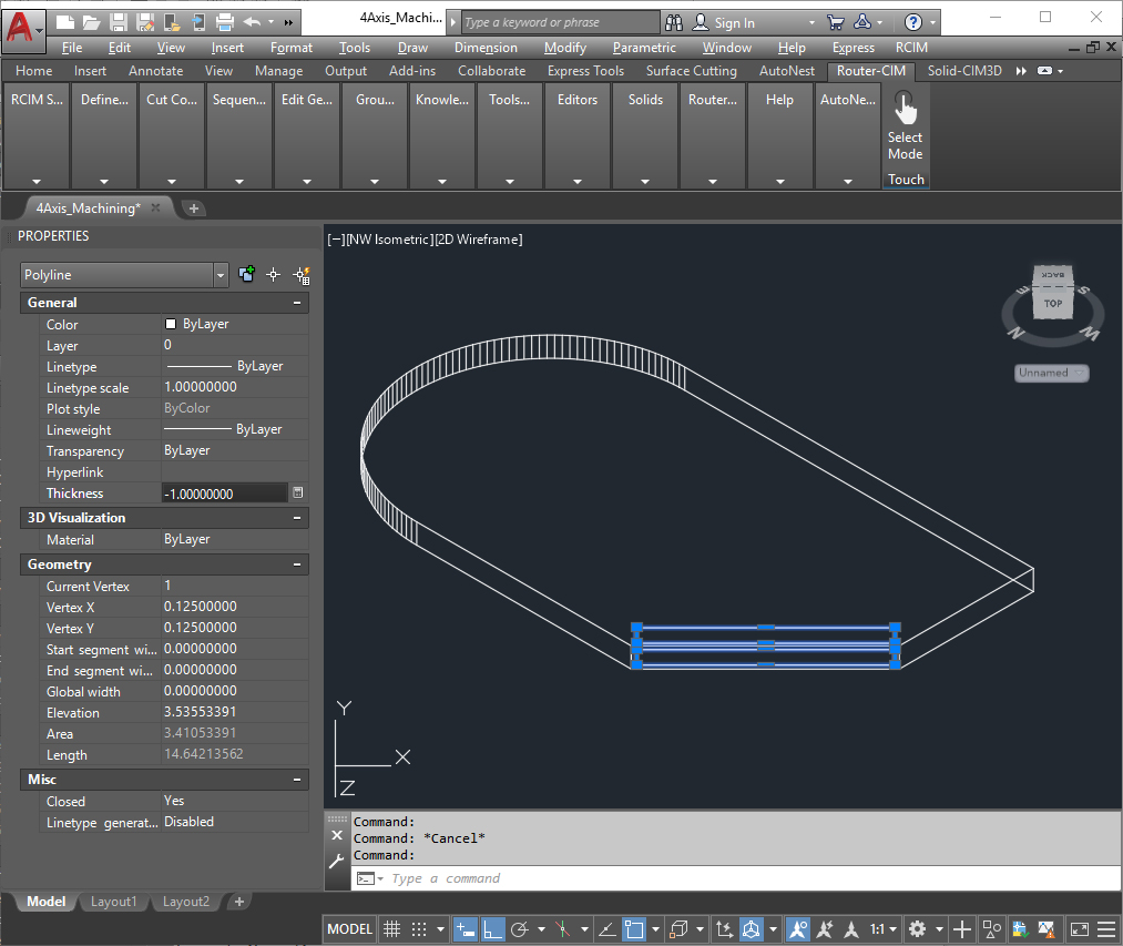
Always Enter Thickness as Negative Value
C. Find the "Thickness" field in this window and change the value to the actual thickness of your part or material. The value should always be a negative. Press the ENTER key to activate the change.
1) To remove the grips (blue squares) from the geometry, move the cursor into the drawing area and press the ESCAPE key.
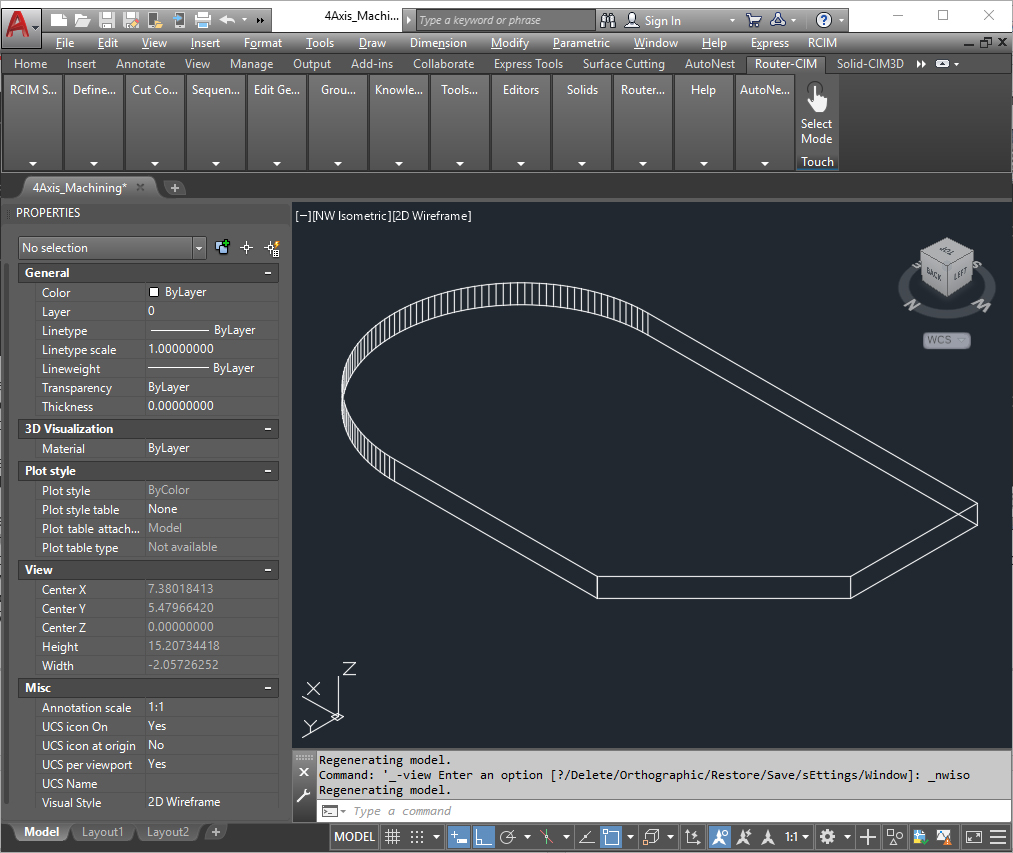
D Change the view to a SE isometric so that you can see the thickness of the part.
3.Change the UCS to match your working surface/plane. All horizontal cuts to be made on the side of the part must be drawn in the proper UCS.
A. Start Router-CIM
B. Decide which side of the part you would like to draw on.
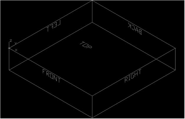
1) If you were to look at a rectangle in a top view, you would see four sides. A Left Side (LS), A Right Side (RS), A Back Side (BS) would be towards the top, and the Front Side (FS) would be towards the bottom.
C. Type the abbreviation of the side you wish to draw a cut on at the command line. RS, LS, FS, or BS.
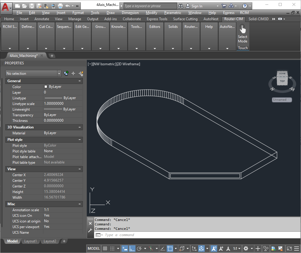
D. Select the origin point. The origin point is going to become the base of the UCS icon
1) If you were to face the side you want to cut on, choose the bottom left corner for the origin. The Origin is Always Lower Left!
| 2) The Endpoint Snap is automatically turned on. When you move the cursor close to the bottom left corner the Endpoint Snap will light up. At this point click to set the UCS. Notice the UCS icon has changed so that the X and Y directions are towards the center of this surface and the Z is pointing away from this surface. |
4. Draw the geometry on this surface as you normally would in a top view.
5. Repeat steps 4 and 5 as needed for each side.
How to draw on a face/side of a part (Non-Planar):
1. Go to the pull down menus at the top of the screen and choose "Tools", "New UCS", "3point" or type UCS in the command line. The default is 3point.
For more information on changing the UCS in AutoCAD, please refer to the AutoCAD Help Manual.
2. Select the origin point. The origin point will become the base of the UCS icon.
A. If you were to face this surface choose the bottom left corner as the origin. Choose the origin with an endpoint snap.
3. Choose a point on the positive portion of the X axis.
A. If you were to face this surface, use the endpoint snap to choose the
bottom right corner.
4. Choose a point on the positive portion of the Y axis.
A. If you were to face this surface, use the endpoint snap to choose the top left corner.
5. The UCS icon should be attached to the lower left corner of the surface and should be in line with the surface. The Z should be pointing away from the part.
6. Draw the geometry to be cut on this surface as you normally would on the top.
7. You can now give the shape you drew thickness (always negative) so that you do not have to specify the depth of cut when making the toolpath.