|
|

|

|
|||
|
|
|
|
Toolpath results from the Expert NURBS Cutter Extension are displayed in either the AutoCAD graphic windows or the NCSurfer module. NCSurfer is a Windows Open GL Application. NCSurfer provides maximum performance. When using NCSurfer, NC code is produced at the same time toolpath is being calculated and displayed.
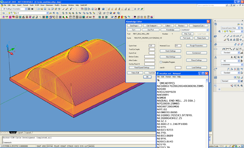
The graphic examples used in this section of the manual were captured from AutoCAD 2008. Toolpath displayed in the NCSurfer Open GL Window will look similar.
Toolpath results displayed in NCSurfer look similar to the figure shown.
Overview:
Router-CIM communicates with the toolpath calculator, or the Expert NURBS Cutter, by using files external to the drawing. You may find some, or all, of the following files being created when using the Expert NURBS Cutter.
"Filename.GEO" contains the NURBS description.
"Filename.PAR" contains parameter controls.
"Filename.O" contains toolpath data that is read by NC Polaris when toolpath is being returned to the drawing.
"Filename.JOB" contains instructional data when toolpath is calculated and displayed using NCSurfer.
"Filename.OB" contains data that enables immediate viewing of toolpath when using NCSurfer.
When multiple machining steps are required for the same group of surfaces or solid (i.e., roughing and finishing), you would run "Cut" multiple times. After running "Cut" the first time, the system recognizes that the <B> ".GEO" file already exists for the drawing name and during subsequent "Cut" requests you are prompted, "Define Surfaces YES/NO". If the operation is intended to address the identical surfaces (or solid), using identical surface tolerances and complimenting entities, you can respond "NO", to the prompt. If a different combination of surfaces (or solid), surface(s) tolerances, or different complimenting entities are required, you must respond "YES", and select the new combination of surfaces (or solid) and complimenting entities for the next operation. Defining Surfaces is a relatively fast function, and it is always safer to respond "YES", and select the surfaces again.
As a general housekeeping rule, after completing an entire job, you can delete the external files to avoid unnecessary buildup of files on the hard disk drive in your computer.
Surface Construction Rules:
A surface must not contain C0 continuity. If unusual toolpath results occur on a given surface, use AMD's Surface Editing Commands to break at C0 to ensure proper performance from the Expert NURBS Cutter Extension.
Occasionally IGES translators will create surface or solid anomalies. Be prepared to use AMD editing features to repair these surface or solid anomalies when unusual toolpath results.
Surfaces created from the 3D Solid should be truncated to ensure proper operation of the Expert NURBS Cutter Extension. Toolpath can be produced directly from the 3D Solid.
A Cavity (female part) must contain a horizontal plane(s) that represents the top of the Cavity or Parting Plane. This Plane(s) can be very narrow to avoid unnecessary toolpath motions. Without the Parting Plane(s) the software can not establish an approach to vertical surfaces, or surface areas that approach near vertical at termination in a Cavity, and results can be unpredictable. A narrow horizontal plane at the top of Cavity wall gives the software an established location to start the toolpath.