|
|

|

|
|||
|
|
|
|
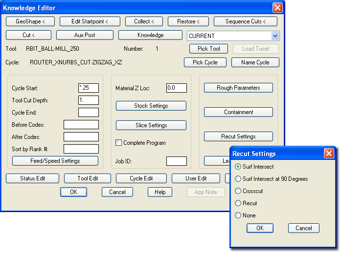
Shown below is the MCADTPC.dwg with the Surface Intersect turned on in Recut Settings.
Using these settings produces a tool path result similar to this:
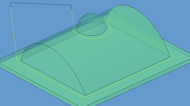
This is a useful feature when a larger tool is used in a roughing or finishing operation and a smaller tool is needed only at the intersections of any geometry to create a smoother transition from one surface to the next.
Be aware that this tool path does not consider the radius offset of the tool, so if you are creating this cut with a ball end mill, and the zero point for the end mill is the radius of the tool, then a Stock Allowance equal to the radius of the tool should be used to make sure the tool path is lofted and the part is not overcut.
Using the Surf Intersect at 90 Degrees creates a Zigzag tool path following the intersection of any of the contours on your part.
Changing the settings above to use Surf Intersect at 90 Degrees will yield a tool path with these results:
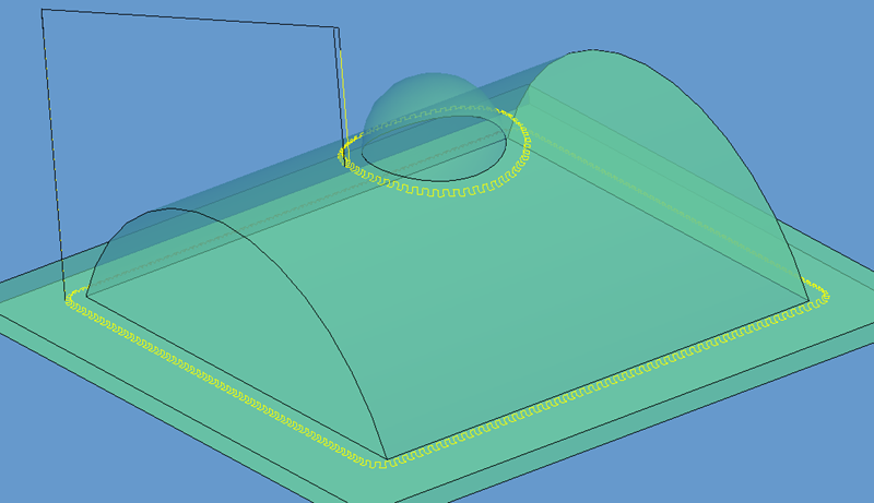
These motions will create many more moves than the first Surf Intersect, resulting in more NC Code, but possibly a smoother transition. The Slice Spacing will usually be changed to yield a much smaller scallop on the part.