|
|

|

|
|||
|
|
|
|
Geometry for horizontal applications must be drawn on the face of the part where the shape is desired and should be drawn to finished size. In other words, draw what you want cut, in the finished size. Parts may be drawn with thickness of the desired depth or the depth may be specified during cut. Depending on the type of cut desired the shape can be open or closed. Start points can be modified to suit the desired starting location of the tool.
Commands have been provided to allow you to draw geometry on the sides of the part easier. The commands are FS for Front Side, RS for Right Side, BS for Back Side, and LS for Left Side. You may return to the World coordinate system with the UCS, command or typing TS, for Top Side. These are simple UCS switches and you can always use the UCS, 3 point command to create a UCS on any face that does not fall into on one of the 4 sides of a part. If you create a UCS of your own, be sure to use the lower left corner of the part as the origin and that the positive Z direction is away from the part and negative Z is into the part. This way your cut will move into the part and not be inside out. The following example shows two pieces of geometry being created on two different sides of a part.
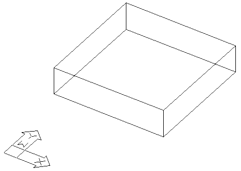
Standard part in World Coordinate System
This part is a standard rectangle drawn with thickness. The UCS Y is pointing at the front side of the part in the illustration above. To draw a shape on the front of your part use the FS command and when prompted for the origin, select the lower left intersection on the front face as your origin.
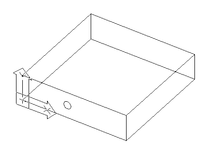
After the FS command is used, you will have a UCS Icon on the front of your part as shown. You can then draw your shape on the front of your part.
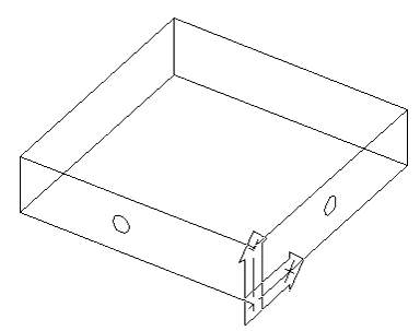
Using the same technique, you can also draw a shape on the right side of the part. Using the RS command, select the lower left corner of the right face. Then draw a circle on the right side.
The shapes you have drawn can now be geoshaped and cut using the standard cut cycles. The next section describes the cutting methods necessary.