|
|

|

|
|||
|
|
|
|
The nested layout displayed after the nesting process in the current AutoCAD session may be edited as a normal AutoCAD drawing. During an editing session of a nested layout, you may wish to make use of a part with an expanded profile by an offset equal to the bridge width. This expanded profile of the part can assist you in manipulating the part to fit a tight corner or space.
When ExpandPart is invoked, the following will appear sequentially at the AutoCAD command prompt :-
Part Expand:
Insertion Pt:
Part Name (? for list) <>:
Cutting Gap <>:
Insertion Pt:
This is to prompt the user the location of the (expanded) part. You can use the pointing device to digitize the screen location or point.
Part Name (? for list)<>
At the 'Part Name (? for list)<>:' prompt, if the ? option is chosen, the following dialog box is displayed:
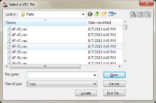
Select a Part form the dialog box and click the “Open” button.
Cutting Gap:
The part will be expanded by the cutting gap as specified here.
Once the entries have been confirmed, ExpandPart will recall the part with an expanded profile. Again the user can now manipulate the part to fit onto the given stock sheet using AutoCAD Modify commands.
The user can then manipulate the part with MOVE, COPY, ROTATE, etc commands of AutoCAD.