|
|

|

|
|||
|
|
|
|
|
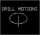
The Drill Motions cycle is the standard drilling cycle in Router-CIM. With Drill Motions, you can drill in one pass, or in several passes with pecking motions.
By default the tool will rapid to the safety plane above the hole, then feed in to the depth of the cut and then rapid out of the hole back up to the safety plane. If you wish to peck drill the hole, you can set multiple depths per pass (peck increments) and the tool will rapid to the hole, feed down to the first depth, the rapid back to the safety plane, then rapid back down to .1 above the next material to be cut, then feed down to the next depth of cut, rapid up to the safety plane, etc. until it finishes the hole.
The drill motions cycle has very few parameters that can be changed as it is the most basic drilling cycle in Router-CIM. |

Drill Motions cut cycle.

Drill Motions parameters
The following parameters effect the toolpath creation:
Safety Plane
The safety plane is the location in the Z axis where the tool can retract to between cuts.
This should always be a value that places the cutter above the part to be cut as each tool change, or index move between cuts is going to start from this point.
Placing an asterisk ( * ) before the number specifies that this value is an absolute point above the part, where leaving this out determines the point to be incremental.
See the Safety Plane section for more information.
Depth Per Pass
This field allows multiple depths of Cut in a single tool path. By setting this number to a value less than the Total Depth of the Cut, you will have multiple passes in the material.
For example, if you have 1" thick material and need to take three passes to Cut through, you would set the Depth/Pass field at .4 (any number between .35 and .5 is valid) and the Total Depth at -1.0. The code generated will produce the first pass at -.4, the second at -.8 and the third pass at -1.0.
In most of the standard Router-CIM cycles the tool paths will ramp down between the Cuts.
Total Cut Depth
The Total Cut Depth is the depth you wish to Cut to, regardless of the number of passes made. It is usually put in as a negative number because Z0 is set at the top of the part. Router-CIM uses this number to calculate the Z axis moves for the Total Depth to Cut into the material. If the Depth/Pass field has a number smaller than this, Router-CIM calculates the number of passes necessary to reach this depth.
You may enable Router-CIM to calculate the depth automatically for you based on the thickness you give a part. To do this place "A" in the Total Cut Depth field, and if you have given you part thickness, Router-CIM will use that value for the Z depth. Remember to give your part negative thickness!
Also, when you give your parts negative thickness, you can use a forward slash (/) followed by a negative value (-.01 for example) in this field. Router-CIM will take the negative part thickness (-.75 for example), and the negative value following the slash and calculate the Total Cut Depth. In this case the part would be cut to -.76.
Feedrate
This field specifies the cutting maximum Feedrate in either inches per minute or millimeters per minute, depending on the mode you are programming in. See the chapter on Advanced Settings for information on how to program variable feed rates.
Spindle Speed
This field sets the spindle speed in rpm's (revolutions per minute). This is a modal field to many machine tools, so if you do not change this field for each Cut with the same spindle, you may only see the output for this setting once although you have made more than one Cut with the same spindle.
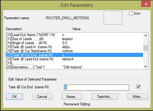
Adding a Dwell/Pause at the end of a Drill Cycle
To add a dwell/pause at the bottom of a Drill Motions cycle, you will need to adjust the following setting in the Drill Motion cycle:
To make this change, go to the Router-CIM Control panel in AutoCAD and select the button for 'Mod Cycle'.
Change Position 17, 'Task @ Cut End (name/N)' in the Drill Motions cycle to DWELL/1 (or the time you want to pause, in seconds). You will get a G04P1 in the code after the tool is at cut depth.
Alternately on newer posts, you can use DWELLX/.1 and get G04X.1.
To make this change, select Position 17, 'Task @ Cut End (name/N)', type in the new value as stated above and hit 'Enter'. You should see the value update in Position 17.
Note: To know which option is right for you, please review your Post Processor's Application Notes.
**Changing values in the cycle parameters may yield unexpected results with some settings or on some geometry. Examine the toolpath and NC Code carefully before running your machine tool if you change these default settings.