|
|

|

|
|||
|
|
|
|
The Flow Cutting cycle will cut perpendicular to the flow lines, but cutting in the direction of the two polylines, so you can use the command NCREVDIR to reverse the direction of the two polylines if desired.
Since there is nothing to contain the tool path when it meets the bottom of the shape, we will use the NURBS Working Area settings to define the top and bottom of the shape so that the tool path does not go below the bottom of the part.
Open MCADCLFLOW.dwg and start Router-CIM. Change your knowledge settings to match the ones below:
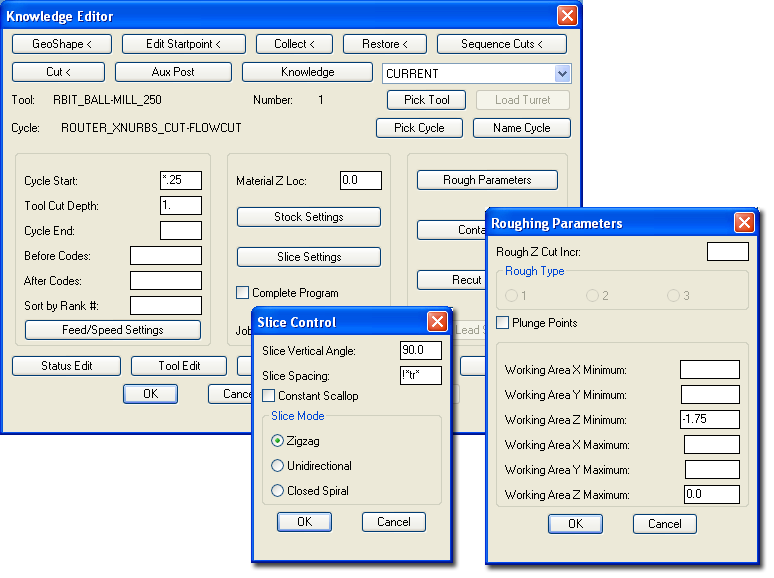
The Roughing Parameters window will allow you to set the Working Area minimum and maximum so that no tool paths cross beyond these areas. Set the Z Maximum to 0.0 which is the top of the part and the Z Minimum to -1.75 which is the bottom of the part and then no tool paths will fall below the part.
Setting the Slice Mode to Zigzag and the Slice Vertical Angle will allow the tool path to make a evenly spaced tool paths without lifting up to the Safety Plane until it reaches the end of the path.
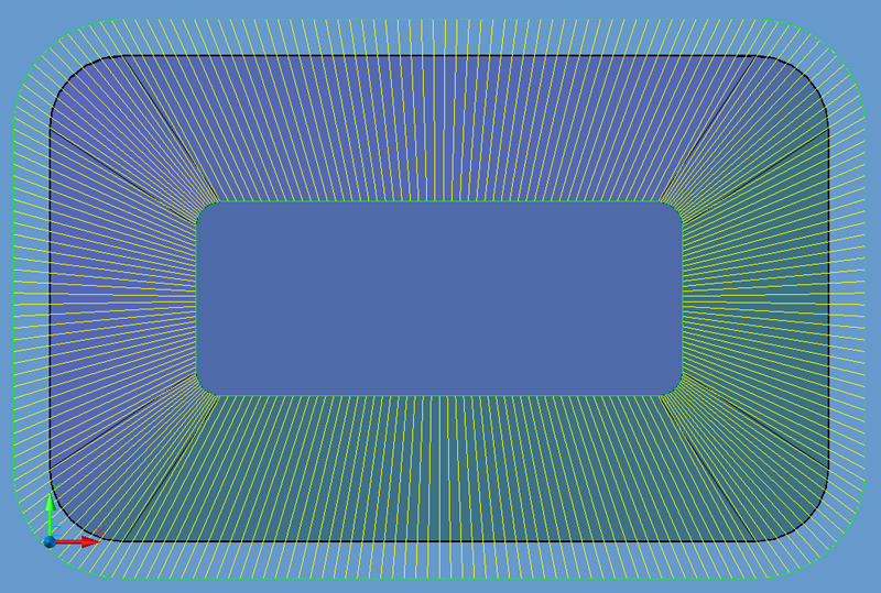
Change your settings to match the ones here and then make a cut, selecting the solid as the shape to cut and the two green polylines as the Flow Lines. If prompted to redefine the surfaces, answer Yes. Your results should look like the one below:
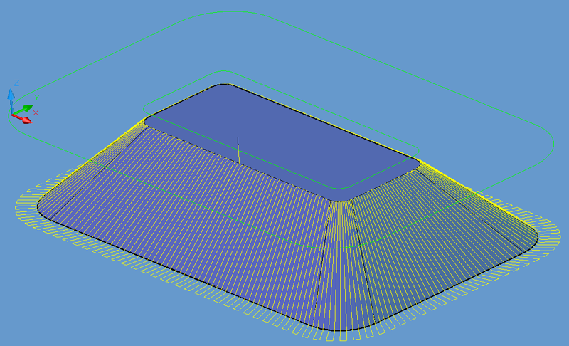
The result of this tool path is evenly spaced tool paths following the contours of the flow lines.