|
|

|

|
|||
|
|
|
|
#
# AutoNEST V9
# Filename = anest.tol
#
# Angle tolerance = Number of vertices(minimum),angular allowance
@ANGTOL
5 2.000000
10 5.000000
20 10.00000
60 20.00000
#
# APERTURE = Size of the aperture
@APERTURE
0.10
#
# Shape Expansion = (Max) angle to trim, trim ratio
@SHP_EXPAND
90 1.0
#
# Arc APPROXIMATION ERROR TOLERANCE (>=0.001)
@ARC_APPROX_ERROR_TOll
0
0.01
@ARC_90_APPROX_NUM
48
@ANGTOL
This parameter is not valid for current version.
@APERTURE
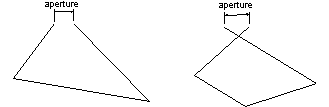
Under this header, you can specify a value (floating point) for the 'Aperture' to be used in SavePart/MirrorPart. This aperture value allows you to control the degree of accuracy when considering whether two distinct end points actually meet.
If the current units is Metric/millimeters, then the value is taken as millimeter(s). On the other hand, if the units is Imperial/inches, then the value is taken as inch(es).
'Aperture' is the degree of accuracy of 2 very close but distinct points to be considered as the same point. Therefore, polygons with vectors not entirely closed or overlapping will still be tolerated if the distance apart is within the default aperture. See below:
@SHP_EXPAND
Under this header, you can specify 2 parameters to control part expansion for cutting gap consideration. These parameters correspond to the maximum angle between 2 vectors at a vertex and the trimming ratio.
Part expansion occurs at two places: during the execution of Nesting or BatchNesting and ExpandPart.
After a part has been expanded, the expanded profile may consist of long narrow and pointed edges. These edges will cause obstruction during the nesting process. It is therefore advisable to trim off these pointed edges. The amount of trimming required for your application is defined here.
The first parameter indicates the range of angles to be considered for trimming. Default is 90, which means that any angle less than 90 will be trimmed. The second parameter specify the amount to be trimmed (ratio of cutting gap) at the vertices of the part/shape. Default is 1.0.
@ARC_APPROX_ERROR_TOLL
Under this header, you can specify 2 parameters to control arc or circle approximation if a part has arcs or circles as profiles.
The first parameter can be set to 1/0. 1 means this parameter is on and 0 means off. If it is off (0), the second parameter will be ignored. Otherwise the second parameter means the error tolerance when approximating arcs or circles. The smaller the value is, the less distortion the approximated profile is. For instance, if the first parameter is set to 1 and the second parameter is set to 0.01, after approximating a circle part, the new part radius will increase at most 0.01.
It’s recommended that the first parameter be set to off (0), i.e., users do not have to use this control parameter. The system will handle arc approximation automatically.
Only when you have some very big parts which are very close to the stock sizes, you may need to set this parameter on to adjust arc approximation to fit the parts. Otherwise you may not be able to nest those big parts.
@ARC_90_APPROX_NUM
This parameter will determine the number of vectors to simulate a 90-degree arc. The higher the number, the more vectors will be generated. Thus affecting the nesting speed, making it to take longer time. Therefore it is suggested that this parameter be maintained unless in special circumstances. For example, a very big curved part that fit into the Stock exactly.