|
|

|

|
|||
|
|
|
|
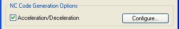
You can apply Acceleration and Deceleration to your NC program by selecting this option. Each motion in the NC Code will be examined for feed requirements and adjusted if necessary. The configuration button allows for the changes to the parameters that control acc/dec.
ACC 'n DEC anticipates change in direction, short moves and/or tight corners, and automatically inserts slow down or control moves into the machine code. ACC 'n DEC was designed to enhance the performance on all machine tools regardless of the controller's ability.
Select the option to turn on Acceleration/Deceleration, and then click on the Configure button to the right to display the Configuration options.
An Acceleration/Deceleration Configuration dialog window will appear.
A brief description for each field follows:
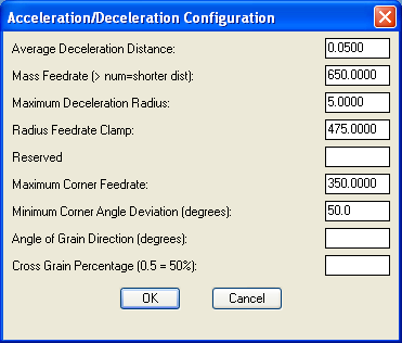
Average Deceleration Distance
Distance to travel to allow for the Mass Feedrate to occur. This is an average because some rounding can occur.
The NCVAR is _ACC_DECDIST.
Mass Feedrate(> num=shorter dist)
The decrease in feedrate from one element to the next over the distance specified by the Average Deceleration Distance. A ration defines the deceleration scale.
The NCVAR is _ACC_DECFEED.
This parameter sets the maximum radius that can be cut at the Radius Feedrate Clamp. Any radius less than this will cause Acc/Dec to be applied.
The NCVAR is _ACC_CLAMPRADIUS.
This is the maximum feed rate that is used on the largest arc setting set in Maximum Deceleration Radius.
The NCVAR is _ACC_CLAMPFEED.
Various values are stored here when the system is in use. Not user configurable.
This is the maximum feedrate that will cut a corner with an angular deviation greater than the Minimum Corner Angle Deviation so that the cutter will not over/under shoot the corner.
The NCVAR is _ACC_CLAMPMIN.
Minimum Angle Deviation of a corner when acc/dec is applied. Any angle deviation between elements or arc sweep that is greater than this value will cause acc/dec to be applied.
Router-CIM will automatically vary the feed rate on angles that are equal or smaller than the angle size set in this field.
The NCVAR is _ACC_ANGDEV.
This is the angle of the grain on the part in degrees. Angles from grain direction are cut at a feedrate scale based on the Cross Grain Percentage.
The NCVAR is _ACC_GRAINDIR.
The percentage of current feedrate to cut 90° across the grain of the part. The value input here (must be in decimal form) will give you a feed rate equal to the percentage, entered in this field, of the maximum feed rate set in the Control Panel.
The NCVAR is _ACC_CROSSGRAINPER.
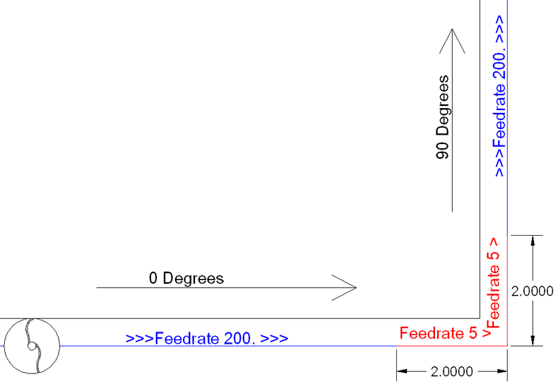
To show how Acc-n-Dec works, we will use a simple example.
EXAMPLE:
A part with an outside corner that has a 90° change between two elements that define the corner. Each element is a line 10 units long. First element is at 0 degrees and the second element is at 90 degrees.

Acc-n-Dec part
Current setting are:
_ACC_DECDIST = 1.0
_ACC_DECFEED = 100
_ACC_CLAMPMIN = 5
_ACC_ANGDEV = 15
_ACC_GRAINDIR = 0.0
_ACC_CROSSGRAINPER = 1.0
_ACC_FEEDRATE = 200 (normal programmed feedrate)
Results:
The angle deviation is greater than _ACC_ANGDEV and the current feedrate exceeds the maximum corner feedrate expressed in _ACC_CORNFEED. Therefore, acc/dec will be applied.
The _ACC_DECDIST/_ACC_DECFEED ratio is applied to the current feedrate to determine a distance from the corner where the _ACC_CORNFEED will be applied. In this example, the distance from the corner is
DIST = ( Programmed Feedrate - Max Corner Feedrate ) * Average Deceleration Distance / Mass Feedrate OR
DIST = (/ (* _ACC_DECDIST (- _ACC_FEEDRATE _ACC_CLAMPMIN)) _ACC_DECFEED) OR
DIST = (/ (* 1.0 (- 200.0 5.0)) 100.0) = 1.95 units
Each of these three formulas are the same.
The first element will be converted into two separate elements so that one can be the deceleration move. The first will be 8 units in length and the second (the deceleration segment) will be 2 units in length.
The first element will have a feedrate of _ACC_FEEDRATE (200), which is the normal programmed feedrate.
The second element will have a feedrate of _ACC_CLAMPMIN (5).
This will allow the machine to ramp down from a feedrate of 200 to a feedrate of 5 over the course of 2 units, just prior to the corner.
Since the _ACC_ACCDIST is zero in this example, the third element (originally the second element at 90°) will then be broken up into 2 pieces equal to the last two on the deceleration side. The first will be 2 units long and have a feedrate of 5 and the second have a feedrate of 200 and the length of 8 units.
Example Code:
N01 G91 G01 X8.0 Y0.0 F200.
N02 G01 X2.0 Y0.0 F5.
N03 G01 X0.0 Y10.0 F200.
If the corner was filleted, the feedrate and length of the deceleration segment would be determined by using the radius feedrate scale ratio (_ACC_CLAMPRADIUS / _ACC_CLAMPFEED).
If _ACC_GRAINDIR is not NIL, then additional limits would be placed on all feedrates that went on the cross grain angle based on the cross grain percentage. By multiplying the current feedrate by the cross grain percentage, a new feedrate is determined.
SPECIAL CONDITIONS:
If an element is not long enough to handle the required de-acceleration segment(dec-segment) length, then the feedrate will be applied to the start of the element. This will, at least, ramp down over the element's length even though full deceleration feedrate will not be achieved at the end of the element.