|
This cycle provides continuous four-axis motion for aggregate moulder heads and fixed moulder heads. Drawing Requirements: This cycle works on standard geometry created by the Geoshape command and is edited with the Start Point Edit command. The shape Polylines must be either a two dimensional polyline in the world plane or a three dimensional shape. Two dimensional shapes on the side of the part do not need to be interpolated in the fourth axis and any or all of the existing cut cycles will work to create valid cutting motions for these shapes. If an invalid shape is selected, the cycle will notify you when you try to cut it. The shape drawn for a fourth-axis cycle must represent the location of the material to be cut. The tool tip will extend into the cut shape by the required depth. The tool path can be shifted down in Z during the cut cycle, or the shape can be drawn at the required Z depth. For clarity, we recommend that 3D shapes be drawn at the appropriate Z depth. If a shape has thickness, this will represent the required Z shift. |

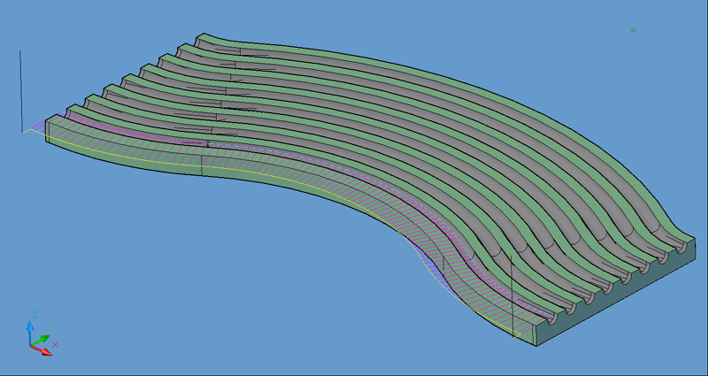
Moulder Head tool path.

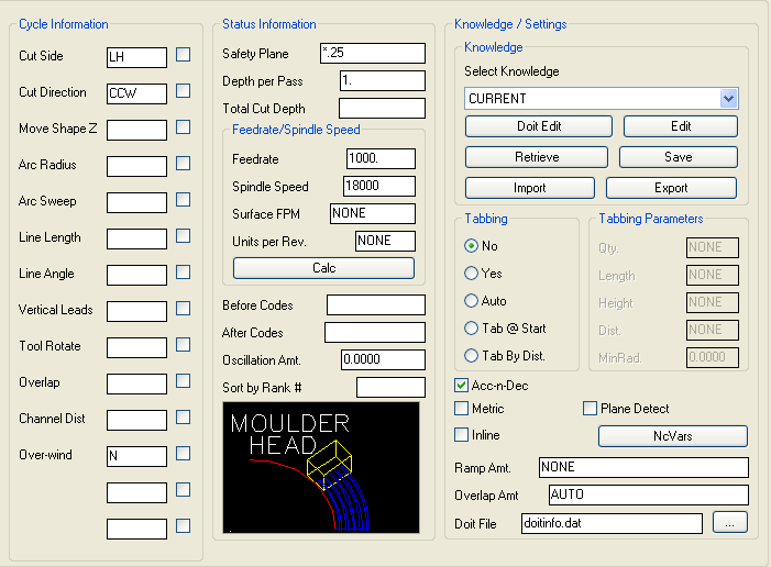
Moulder Head parameters.
The following parameters effect the toolpath creation:
Cut Side
Cut Side is the side of the Geoshape that the toolpath will be created on. For instance Plunge-Outside (Plunge-O) will have the toolpath on the outside of the shape. Valid entries for this field are Outside, Inside, RH (Right Hand) and LH (Left Hand).
Select the Cut Side section for more information.
Cut Direction
The direction of the cut can only be clockwise (CW) or counter-clockwise (CCW). This even applies to open shapes where this direction really has no meaningful relationship to the geometry selected. Any closed shapes should have the direction set accordingly and any open shapes should be set to CCW as all shapes in AutoCAD and Router-CIM are CCW by default.
Select the Cut Direction section for more information.
This value sets the Z height of the tool path. The tool path can be moved up or down with a positive or negative number in this position. Note that this is the Z position in the world coordinate system. The distance into the material horizontally is the Total Cut Depth.
Lead In and out moves can have an arc lead. The radius of the arc is specified here. There can be two values placed in this position, the first being the lead-in and the second being the lead-out.
The degrees of sweep in the arcs for the leads can be specified here. There can be two values placed in this position. The first would be for the lead-in and the second would be for the lead-out.
The length of the lead-in and lead-out line. There can be two values here, one for the lead-in and one for the lead-out.
The angle of the leads, specified in degrees. There can be two values here, one for the lead-in and one for the lead-out.
Specify Y for yes, or N for no. If Yes is selected, then the lead-in and lead-out moves will be in the vertical plane, instead of the XY horizontal plane.
Specify Y for yes, or N for no. If Yes is selected, then the lead-in and lead-out moves will be cause the tool to rotate into the lead-in and lead-out. This is only valid for leads where Vertical Leads is set to N.
Specified as a numeric distance. The overlap is the distance the tool travels as it crossed the start point. This is useful when removing witness marks from the lead-in.
If Vertical Leads is set to Y, then you can specify a Channel Distance to make the cutter ramp into the cut following the contour. Setting the distance to a small number will cause a steep, sharp ramp, and setting it to a larger number will make a longer, more gradual ramp. There can be two values here, one for the lead-in and one for the lead-out.
The safety plane is the location in the Z axis where the tool can retract to between cuts.
This should always be a value that places the cutter above the part to be cut as each tool change, or index move between cuts is going to start from this point.
Placing an asterisk ( * ) before the number specifies that this value is an absolute point above the part, where leaving this out determines the point to be incremental.
Select the Safety Plane section for more information.
This field allows multiple depths of Cut in a single tool path. By setting this number to a value less than the Total Depth of the Cut, you will have multiple passes in the material.
For example, if you have 1" thick material and need to take three passes to Cut through, you would set the Depth/Pass field at .4 (any number between .35 and .5 is valid) and the Total Depth at -1.0. The code generated will produce the first pass at -.4, the second at -.8 and the third pass at -1.0.
In most of the standard Router-CIM cycles the tool paths will ramp down between the Cuts.
The Total Cut Depth is the depth you wish to Cut to, regardless of the number of passes made. It is usually put in as a negative number because Z0 is set at the top of the part. Router-CIM uses this number to calculate the Z axis moves for the Total Depth to Cut into the material. If the Depth/Pass field has a number smaller than this, Router-CIM calculates the number of passes necessary to reach this depth.
You may enable Router-CIM to calculate the depth automatically for you based on the thickness you give a part. To do this place "A" in the Total Cut Depth field, and if you have given you part thickness, Router-CIM will use that value for the Z depth. Remember to give your part negative thickness!
Also, when you give your parts negative thickness, you can use a forward slash (/) followed by a negative value (-.01 for example) in this field. Router-CIM will take the negative part thickness (-.75 for example), and the negative value following the slash and calculate the Total Cut Depth. In this case the part would be cut to -.76.
This field specifies the cutting maximum Feedrate in either inches per minute or millimeters per minute, depending on the mode you are programming in. See the chapter on Advanced Settings for information on how to program variable feed rates.
This field sets the spindle speed in rpm's (revolutions per minute). This is a modal field to many machine tools, so if you do not change this field for each Cut with the same spindle, you may only see the output for this setting once although you have made more than one Cut with the same spindle.
**Changing values in the cycle parameters may yield unexpected results with some settings or on some geometry. Examine the toolpath and NC Code carefully before running your machine tool if you change these default settings.